Dell PN350M stylus repair
Some time ago, I was given a broken Dell PN350M N-Trig/MPP stylus. I confirmed that it was indeed broken, and seeing no ways for a non-destructive disassembly, I shelved it for some later day when I was feeling less squeamish about scratching it up.
 The stylus
Over a year later, that day is today. Thankfully, the stylus came with the full suite of boring regulatory information, so I noticed that its regulatory ID is given as “SPEN-DEL-01”. Looking that up finds an FCC listing not by Dell, but by “Sunwoda Electronic”, presumably the OEM. Thankfully they didn’t skimp on documentation, so the user manual gives lots of specs Dell would never divulge, an engineering drawing of the pen, and part of Dell’s design spec. There are also photos of the inner PCB1.
The engineering drawing shows two threads: one separating the cap, the other at the tapered tip-end. Turning it didn’t seem possible when I tried it first, but emboldened by this knowledge, I managed to unscrew the end in a few minutes just by hand, without scratching the surface finish.
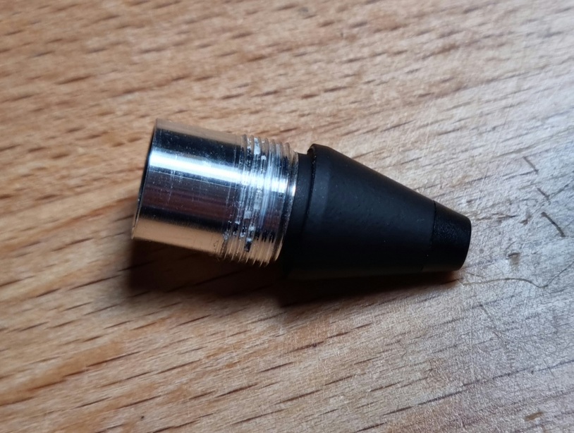
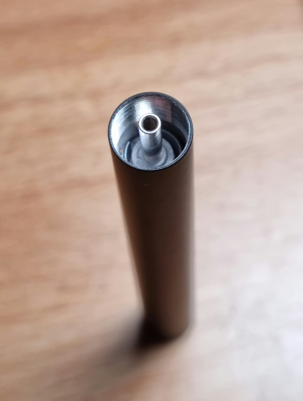
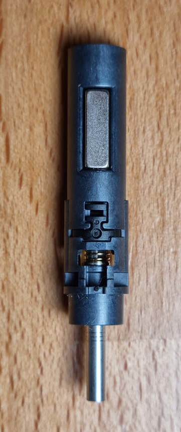
Pulling on the exposed metal shaft (into which the tip would normally slot) slid out the insides without friction. If you’re doing this, make sure not to let the buttons fall out! They’re a pain to get back in.
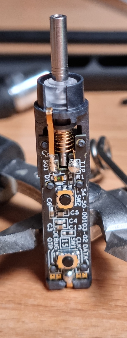
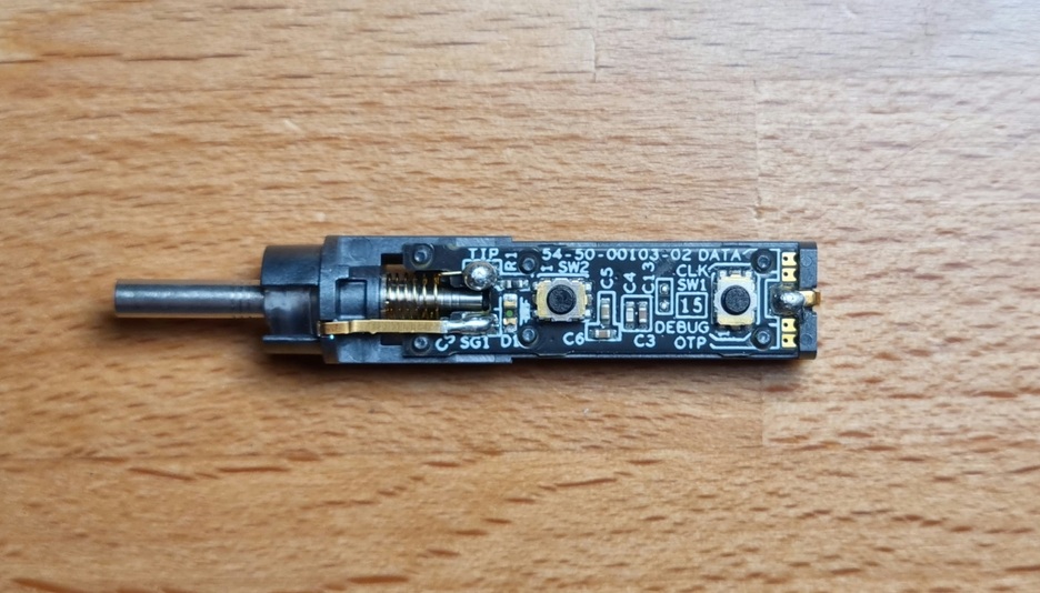
Looking at the PCB, what you see on the right is the end that would normally contact an inserted battery’s positive terminal. The negative’s path is more circuitous: First it is contacted by the battery cap’s spring, then it goes through its metal body, through the thread connecting it to the main body, then through the thread connecting that to the tip-end, which then finally presses onto the gold-plated metal piece soldered to pad SG12.
The rest of the PCB is pretty minimalistic, everything is handled by an ASIC on the other side of the board. Getting to it would require removing heat-stakes and desoldering a few connections.
Thankfully I didn’t have to, since when I reassembled the pen and inserted a battery, it sprang to life without any issues! It seems some part of the negative pole’s journey was interrupted by age, and re-screwing everything fixed the connection.
Aside: Working principle
When looking at the PCB shots re-published by the FCC, I noticed that it has what looks like an LED-photodiode pair aimed at the central shaft. I can’t figure out what they’d be for, though. The first idea is line-of-sight detection, but the shaft is permanently inserted. I wobbles a bit, so maybe some time-of-flight sensing could be useful, but I don’t see how this arrangement would help.
Besides that, I expected to find a force cell somewhere, but the shaft is only loosely coupled to anything. This patent suggests that this might be accomplished by some kind of inductive sensing.